How To Make Menu www.punj.co.uk


Punj Tips and Tricks
at http://www.punj.co.uk
Basic Electronics
Introduction to basic electronics
On
this page we are going to try and provide a very basic understanding in
the knowledge of a very specialist technological field known as
electronics. The understanding of electronics can be very complicated
and covers a great area. We however are going to try and explain the
very basics in this highly knowledgeable specialist field.
Electronics
will be found every where in the modern day. At home or work you will
come across devices and gadgets which rely solely on their design and
production in the provision of electronics. These so called electronic
devices help us in our every day needs in today's modern world.
Everyone
today is exposed to electronic devices in one way or another.
Everyone can benefit from the additional knowledge of electronics. Electronics in simple terms is the
flow of electrical charges to circuits to accomplish specific tasks.
Basic
electronics is all about electrical components and circuits consisting
of those components. Common components are resistors, capacitors,
inductors, transistors, and integrated circuits. These components
can be interconnected with conductors, either by physical wires or
printed circuits boards. Each circuit will have a specific job and task
to work satisfactorily. Components are also interconnected to
perform specific tasks. Below we shall take a very basic look and
understanding on some
of these electronic components. We hope our readers appreciate that on
this page we will be covering a very small part of this very large
technological subject
Basic
electronic components
Resistors and resistance
circuits
Resistance
can be explained as the opposition to a flow of current. The unit of
the resistor is often represented by the Greek letter omega The
practical unit of resistance is called the ohm.. Most resistors look
like the components as shown in the image below
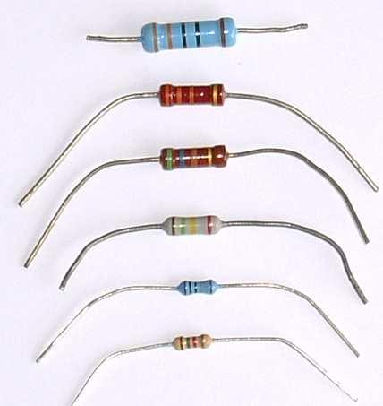
Resistors normally determine
the flow of electrical current in an electrical circuit. Where there is high resistance in a
circuit the flow of the current is small, where the resistance is low
the flow of the current is large. Resistance, voltage and current are
connected in an electrical circuit by Ohm’s Law
Resistors are too small to have numbers printed on them and so they are
marked with a number of coloured bands. Each colour stands for a
number. Three colour bands shows the resistors value in ohms and the
fourth shows tolerance. Resistors can never be made to a precise value
and the tolerance band (the fourth band) tells us, using a percentage,
how close the resistor is to its coded value.
Resistors can generally
be found connected in series (end to end), or in parallel (across one
another), or in a combination of series and parallel.
The value of a resistor can be written in a variety of ways. Some
examples are given below:
47R means 47 ohms
5R6 means 5.6 ohms
6k8 means 6800 ohms
1M2 means 1 200 000 ohms
A common value is 'K' which means one thousand ohms. So if a resistor
has a value of 7000 ohms it can also be said to have a value of 7K.
Capaciitors
and Capacitance
A
capacitor is a device that stores an electrical charge when a potential
difference (voltage) exists between two conductors which are usually
two plates separated by a dielectric material (an insulating material
like air, paper, or special chemicals between two sheets of aluminum
foil).
Capacitors store electric charge. They can be used as filters, AC
coupling capacitors and as by-pass
capacitors. They are also used in conjunction with resistors and
inductors to form tuned circuits and timing circuits. A
capacitors value C (in Farads) is dependent upon the ratio of the
charge Q (in Coulombs) divided by the V (in volts). Common
capacitors come in values of micro farads or Pico farads. Often
you will have to convert between Pico farads and micro farads.
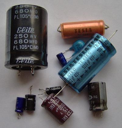
Measuring
capacitance requires a capacitance meter. When measuring or testing
capacitors great care must be taken that the capacitor is completely
discharged. Failure to carry out this vital procedure could lead to an
electric shock or damage to your test equipment.
You can read our review on a great meter for testing capacitors by
going to this page ESR Micro Capacitance Meter
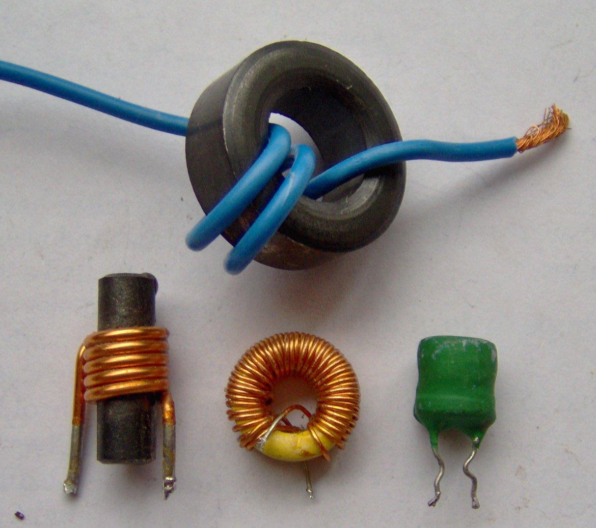
Inductors
Inductors
are usually made with coils of wire. The wire coils are wound around
iron cores, ferrite cores, or other materials except in the case of an
air core inductor where there is no core other than air. The inductor
stores electrical charge in magnetic fields. When the magnetic field
collapses it induces an electrical charge back into the wire.
Inductors are associated with circuit capacitance and can form a tuned
circuit and resonate at a particular frequency.
Two
coils close to one another, as found in transformers, would transfer
charge from one coil to the other. This is called mutual
inductance.
The electrical property of an inductor is called inductance and the
unit for this is the henry, symbol H. Inductors are mainly used
in tuned circuits to block high frequency AC signals (they are
sometimes called chokes). They pass DC easily, but block AC signals,
this is the opposite of capacitors.
An inductor may be connected either way round and no special
precautions are required when soldering.
Diodes
Diodes
will allow electricity to flow in only one direction. Diodes normally
have markings to shows the direction in which the current can flow.
Diodes are the electrical version of a valve and early diodes were
actually called valves.
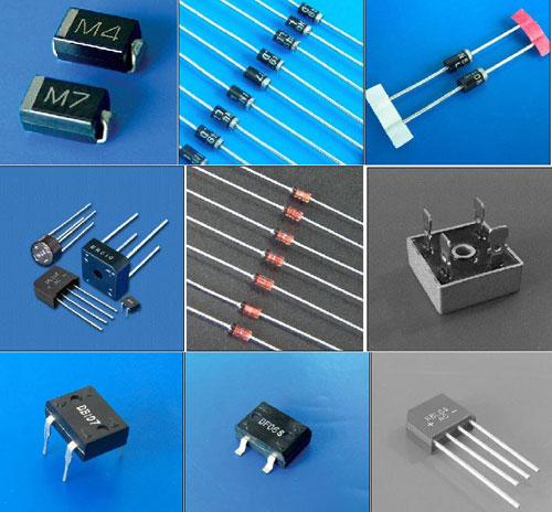
When
using and connecting diodes within a circuit they must be installed the
correct way around. Diodes always have markings to show the correct
polarity. Basic diodes are found to be used in the following ways.
Signal diodes - Signal diodes
are used to process information or electrical signals in circuits, so
they are only required to pass small currents of up to 100mA. General
purpose signal diodes are made from silicon and have a forward voltage
drop of 0.7V.
Germanium diodes have a lower forward voltage drop of 0.2V and this
makes them suitable to use in radio circuits as detectors which extract
the audio signal from the weak radio signal.
Rectifier diodes - Rectifier
diodes are used in power supplies to convert alternating current (AC)
to direct current (DC), a process called rectification. They are also
used elsewhere in circuits where a large current must pass through the
diode.
All rectifier diodes are made from silicon and therefore have a forward
voltage drop of 0.7V. The 1N4001 is suitable for most low voltage
circuits with a current of less than 1A.
Bridge rectifiers - There are
several ways of connecting diodes to make a rectifier to convert AC to
DC. The bridge rectifier is one of them and it is available in special
packages containing the four diodes required. Bridge rectifiers are
rated by their maximum current and maximum reverse voltage. They have
four leads or terminals: the two DC outputs are labelled + and -, the
two AC inputs are labelled ~.
Zener diodes - Zener diodes
are
used to maintain a fixed voltage. They are designed to 'breakdown' in a
reliable and non-destructive way so that they can be used in reverse to
maintain a fixed voltage across their terminals. Zener diodes can be
distinguished from ordinary diodes by their code and breakdown voltage
which are printed on them. Zener diode codes begin BZX... or BZY...
Their breakdown voltage is printed with V in place of a decimal point,
so 4V7 means 4.7V in this example.
Transistors
Transistors
amplify current, they can be used to amplify the small output current
from a logic IC so that it can operate a lamp, relay or other high
current devices. In many circuits a resistor is used to convert the
changing current to a changing voltage, so the transistor is being used
to amplify voltage. A
transistor may be used as a switch (either fully on with maximum
current, or fully off with no current) and as an amplifier (always
partly on). The amount of
current amplification is called the current gain, symbol hFE.
There
are two types of the standard transistor, NPN and PNP, with different
circuit symbols. The letters refer to the layers of semiconductor
material used to make the transistor. Most transistors used today are
NPN because this is the easiest type to make from silicon. The
transistor leads are normally labelled base (B), collector (C) and
emitter (E).
The labelled terms refer to the internal operation of a transistor but
they are not much help in understanding how a transistor is used, so
just treat them as labelled A Darlington pair is two transistors
connected together to give a very high current gain.
Transistors have three leads which must be connected the correct way
round. Wrongly connecting a transistor will cause damage instantly when
switching the device on.
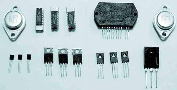
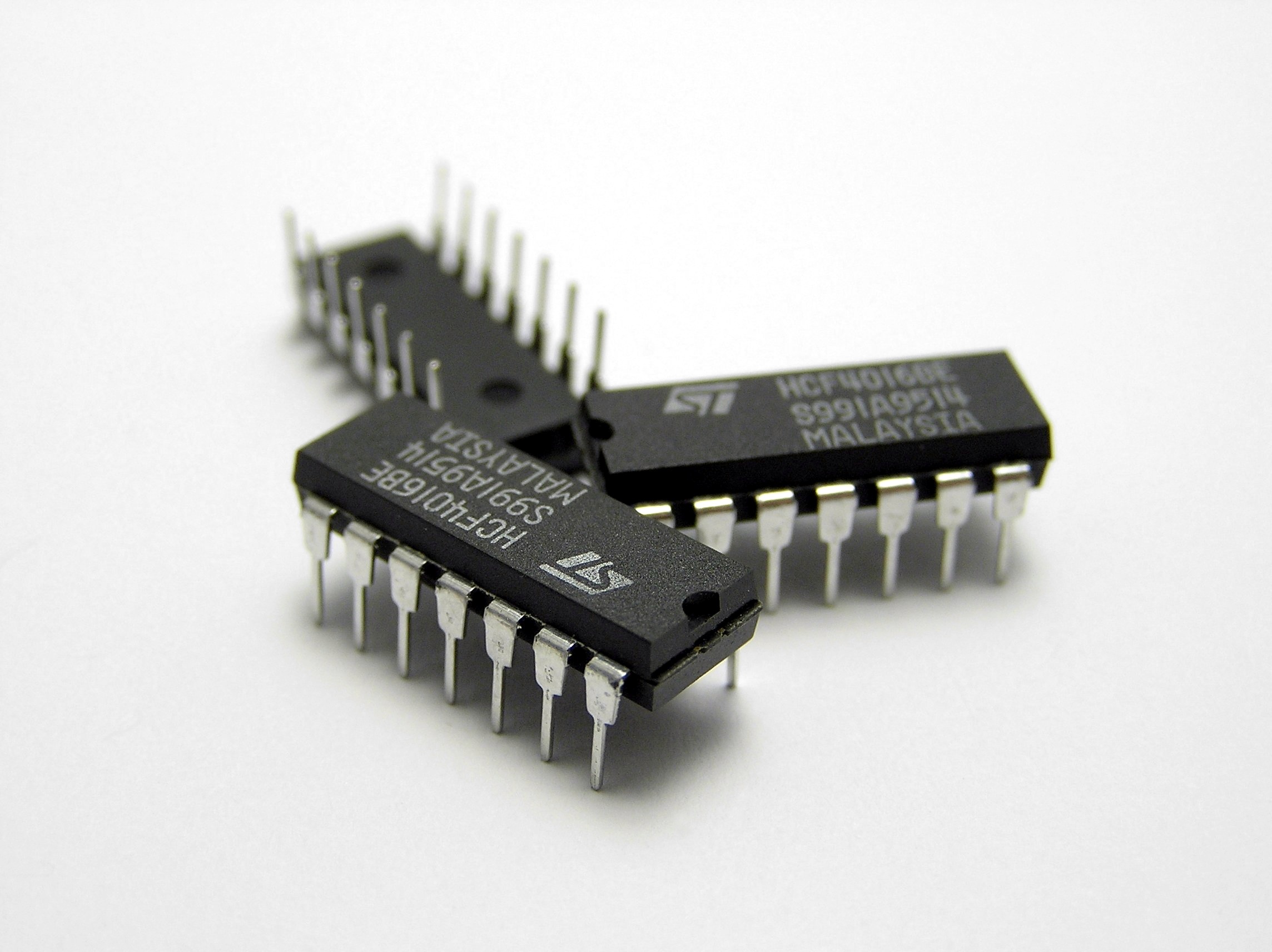
Integrated Chips (IC's)
Integrated
Circuits are usually known and called ICs or chips. They are complex
circuits which have been etched onto tiny chips of semiconductor
(silicon). The chip is packaged in a plastic holder with pins spaced on
a 0.1" (2.54mm) grid which will fit the holes on a standard stripboard
and breadboards. Very fine wires inside the package link the chip to
the pins
IC's
are very sensitive to static and can be damaged when you touch them
because your body may have become charged with static
electricity. IC's will normally be supplied in anti-static
packaging with a warning label and they should be left in this
packaging until you are ready to use them. It
is usually adequate to earth your hands by touching a metal water pipe
before handling the IC but for the more sensitive (and expensive!) IC's
special equipment is available, including earthed wrist straps and
earthed work surfaces.
Logic IC's
- Process digital signals and there are many devices, including logic
gates, flip-flops, shift registers, counters and display drivers. They
can be split into two groups according to their pin arrangements: the
4000 series and the 74 series which consists of various families such
as the 74HC, 74HCT and 74LS.
74 Series -
There are several families of logic ICs numbered from 74xx00 onwards
with letters (xx) in the middle of the number to indicate the type of
circuitry, eg 74LS00 and 74HC00. The original family (now obsolete) had
no letters, eg 7400.
The 74LS (Low-power Schottky) family
(like the original) uses TTL (Transistor-Transistor Logic) circuitry
which is fast but requires more power than later families. The
74HC family has High-speed CMOS circuitry, combining the speed of TTL
with the very low power consumption of the 4000 series. They are CMOS
IC's with the same pin arrangements as the older 74LS family. Note that
74HC inputs cannot be reliably driven by 74LS outputs because the
voltage ranges used for logic 0 are not quite compatible, use 74HCT
instead.
The 74HCT family is a special version
of 74HC with 74LS TTL-compatible inputs so 74HCT can be safely mixed
with 74LS in the same system. In fact 74HCT can be used as low-power
direct replacements for the older 74LS IC's in most circuits. The minor
disadvantage of 74HCT is a lower immunity to noise, but this is
unlikely to be a problem in most situations. Beware that the 74 series is often still
called the 'TTL series' even though the latest IC's do not use TTL.
PIC Microconroller - PIC
is known as a Programmable Integrated Circuit microcontroller, or a
'computer-on-a-chip'. They have a processor and memory to run a program
responding to inputs and controlling outputs, so they can easily
achieve complex functions which would require several conventional ICs.
Programming
a PIC microcontroller may seem daunting to a beginner but there are a
number of systems designed to make this easy. Programs can be written
in a simple version of BASIC or using a flowchart.
We
have now covered the very basics in this vast field called electronics.
Hopefully you can now have a very basic understanding of the
electronics world. More detailed information on this subject can be
easily found by just searching for content on the internet. We hope you
have found our introduction to electronics of interest. If you have
enjoyed reading this page or would like to comment then you can do so
by following this link. Comments & Suggestions
Return
to punj.co.uk home
Keep
up to date with
our blog at punj
Punj
Telecom repairs page
This site
is © Copyright of www.punj.co.uk
1998-2015, All Rights Reserved. http://www.punj.co.uk and the punj blog owners