On this
page we are going to show you an example of bad capacitors on a
computer motherboard. We will discuss the motherboard specification,
the symptoms of this problematic board and the final repair outcome of
this motherboard.
We
were recently given a computer which would itermitently freeze and
lockup especially on online gaming. Most of the time when the computer
froze the speaker would also give a constant static noise..
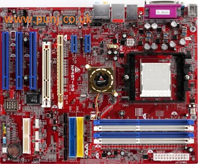
On opening the computer casing we noted that the motherboard was a
Biostar NF4ST-A9 with an AMD Athlon X2 3800+ 2Ghz Dual Core socket 939
CPU.
The main memory ram installed was 4 sticks of DDR1 memory totalling
2GB. The graphics dispaly was via the PCIe HD4350 graphics card
with the TV monitor plugged into the HDMI port. Storage was supplied by
the Western Digital 500GB SATA
hard disk drive.
Straight away we noticed when looking at the main motherboard that one
of the electrolytic capacitors was bulging and had leaked.
This capacitor was located near to the CPU heatsink.
Actual component testing
on todays modern circuit boards can be quite difficult without test
instruments. The use of specialist test meters and equipment is the
only way to satisfactorily test components.
Not everyone will have access to the specialist test equipment. We can
however sometimes assume failure of some components by visually looking
at these components.
Visual checking of a capacitor to determine failure is one example
where an electrolytic capacitor will look different to a good
electrolytic capacitor on a circuit board.
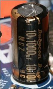
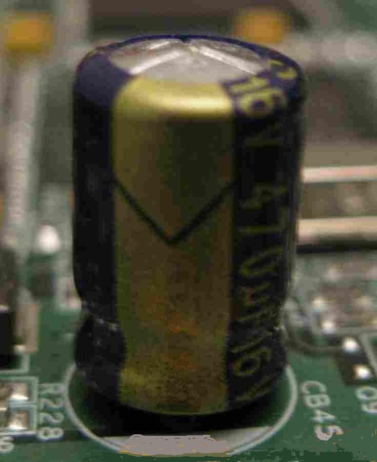
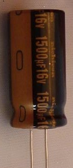
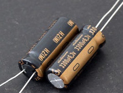
Below the image on the left shows what a good capacitor should look
like. On the right image we show an example of a bad capacitor. You
will notice that the bad capacitor casing on top is bloated where as
the good capacitor on the top is completely flat..
Image on the left shows a Good Capacitor ---- Image on the right shows a Bad Capacitor
You
may also notice that a bad capacitor like ours had leaked from the top or bottom
with its electrolytic content. Capacitors can also go bad and show no
visible signs. The only way to test a capacitor which shows no visible
signs of failure is to measure the capacitors ESR and capacitance value
using an ESR meter. You can read our review on a great budget meter
called an ESR Micro which can be used for the correct method for
testing capacitors on http://www.punj.co.uk/punjwebfiles/electronics/microesr.html
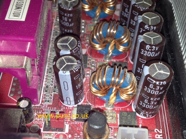
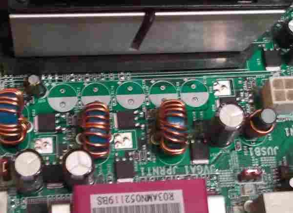
On our motherboard we had five 3300uf 6.3V capacitors located near to
the CPU and three 1500uf 16V capacitors elsewhere on the board which we suspected as bad capacitors.
As
you can see on the image above the four capacitors which are next to
the CPU heat sink are showing no visible signs of breakdown but the
fifth capacitor missing from our image was bulging with some signs of
electrolytic leakage.
All these capacitors were manufactured by Nichicon and from their KZG series.
We no from experience that this series of capacitor can oftern fail
showing no signs of any defects. Indeed it is recommended that all
capacitors within the motherboard from the KZG series be replaced
regardless of the current condition.
Nichicon no longer manufacturer the KZG series of capacitor but do
manufacturer other series which would be a good replacement and better
quality for our motherboard.
The replacement capacitors we chose for our motherboard were the
Nichicon from their HZ series. We confirmed from the manufacturers data
sheet that this replacement would be of better specification for
replacing our bad capacitors. It is very important that the replacement
capacitors specification is of a similar or higher quality as not all
series of capacitors are suitable for the design of their functionality.
It is advisable prior to removing the capacitors to make a sketch or
take photographs of where the capacitors are located on the
motherboard. The last thing you would want is to forget which capacitor
came from which location on the motherboard. You certainly don't want
to be putting in the wrong capacitors in the wrong location of the
motherboard. You must also take your time and double check each task
when carrying thiese procedures.
Removing capacitors on modern motherboards can be quite tricky. Most
modern motherboards are made of multiple layers interconnecting each
layer. Care must taken that the layers not visible on a motherboard are
not damaged when soldering or de-soldering. When removing these
components the soldering iron must be clean and hot enough to melt the
solder but not to hot that it will cause heat damage to the circuit
board tracks which may be visible or located within the un-visible
layers of the board. A good tip is to heat the lead of the capacitor
and wiggle and pull on one side then heat the other lead and do the
same to that. Eventually the capacitor will come out. The other problem
you may encounter is once the capacitor has been removed the component
hole is completely blocked with solder. Our tip to unblock these holes
is to apply some more solder on the blocked hole and then use a solder
sucker tool to suck the solder out of the hole. If you find that the
solder sucker is not totally unblocking the component hole then pushing
a stainless steel needle into the hole while holding the hot soldering
iron on to the blocked hole sometimes helps. The hot solder should not
stick to the stainless steel needle and therefore this tip should work.
Once the capacitors have been removed you should inspect the
motherboard with a magnifying glass to ensure that no solder that
should have been removed is shorting the board. If all looks well then
you are ready for the next procedure.
If you look at the image above, of the motherboard with the removed
capacitors you will notice where the capacitors came out there is a
symbol of a circle with one side coloured white. This white coloured
area shows us the polarity of the capacitor to be negative on this
white coloured side. The polarity of the capacitor is very important for
the correct function of the capacitor.
On our motherboard we chose our replacement of capacitors manufactured Nichicon. We wanted to ensure our replacement
capacitors were sourced from reputable manufactures. We chose the same
value capacitance and voltage for our replacement capacitors. You can
use higher voltage capacitors but you should ensure that the capacitor
leads are not to thick to put back into the motherboard component hole.
Once the new capacitors have been put into the motherboard always
double check before soldering that the correct values have been used.
It is quite easy to confuse and mistakenly use a 100uf capacitor
instead of the correct value 1000uf. Also check that you have inserted
correctly the polarity of the capacitor.
When soldering the new capacitors make sure that your soldering iron
tip is clean and tinned. Then solder your new replacement capacitors
ensuring that you obtain a good clean shiny soldered joint.
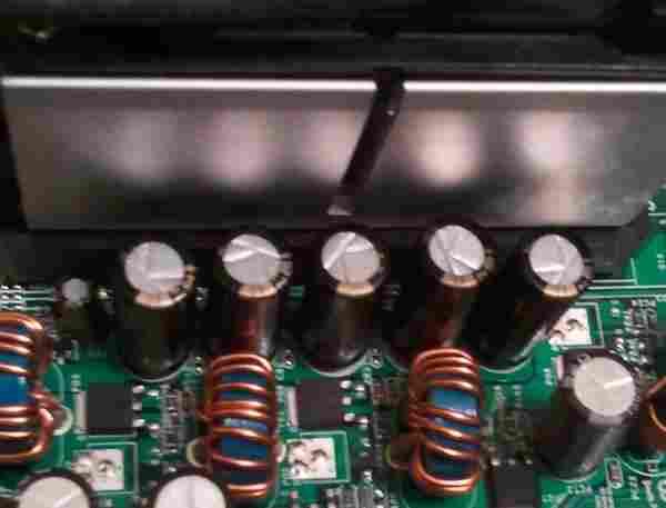
Above you will see an image of the motherboard with the new replaced
capacitors.
On completion of the soldering task you may want to clean the excess
flux deposits left behind by the soldering. We normally use a cotton
bud dipped into alcohol which works fine for us. Now is also a good
time to re-check the new capacitors to ensure that the correct values
have been used and that the motherboard is clean and ready for
re-installation.
On re-installation of the motherboard into the PC tower case we ensured
that all the add on cards and memory went back into the same slots as
originally found prior to stripping out the motherboard. If you do end
up using a different slot for your add on card or memory you may find
that the PC will not re-boot until you have cleared the CMOS and loaded
the default factory settings. Your motherboard manual should help to
locate the correct jumper on the motherboard to clear CMOS if you find
you have a blank screen.
For us the motherboard switched on straight away and booted straight in
to the Windows 7 operating system with out any problems. We used Everest to
stress test our repaired motherboard for two hours without encountering
any problems.
On completion we decided to test the faulty removed capacitors using
the ESR Micro V4 for measuring the capacitance and ESR
readings.
A good 3300uf capacitor should give us a measured capacitance reading
of the same value subject to the manufactures tolerance of about 10%
either side of the tolerance value. We would also expect the ESR
measured reading to be approximately 0.02 ohms. Testing the
removed bulging capacitors gave us typical measured readings of 4510uf
capacitance and an ESR measurement of 0 ohms for the 3300uf capacitor.
This clearly showed that these capacitors were faulty and if left in
their current state they could have caused more severe problems to
other components on the motherboard.
The ESR reading is very important and the typical ESR measurement
of 0 ohms showed that these capacitors were generally shorting.
If a capacitor is shorted then the DC resistace will be equal to zero.
The majority of ESR meters detecting this failure will indicate the
measured reading as 0 (zero) ohms.
In our final conclusion we can say that replacing the bad capacitors on
this motherboard completely resolved our previous problematic issues.
Our motherboard seems also quicker in load times and faster over all.
The whole cost of the five 3300uf 6.3V and two 1500uf 16V
capacitors was £10.73 GBP including shipping from a reputable supplier
within the USA. The whole task of replacing the
capacitors took approximately thirty minutes.
We hope our readers have enjoyed this
article on replacement of faulty bad capacitors on computer
motherboards and will come back to
www.punj.co.uk for our views on more technological
products.
Watch the video below and see bad capacitors on other motherboards
The second video shows capacitor being replaced on a imac G5